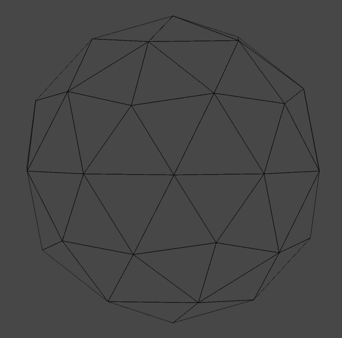
Figure 1. Wireframe of 3D model.
In our second Shader Adventure we will use plane’s normal to create basic holographic effect. We start with a super simple shader that paints 3D model’s planes according to a value of dot product between a plane normal and a view direction. Planes orientated parallel to the view direction, (these planes in our model are located in the middle part of Fig. 1.) will be painted by white colour. Planes, which in fact could not be seen, oriented perpendicular to the view direction will be marked by red colour. Any orientation of a plane between 0 deg and 90 deg will yield reddish colour. We will make that the green and blue channels values will depend on angle between a normal vector of plane and a view direction. And that will produce reddish colour of planes. To demonstrate this effect I will use model presented on Fig. 1. The triangles represent model planes.
So go to github and grab the base shader or generate in Unity3D the UnLit shader (2017.2.1p4 version of Unity3D I am currently using). First let’s make change to shader code and after that we will discuss the effects of this changes. Start with:
 - in AppData struct add: float3 normal : NORMAL;
 - in v2f struct add: float3 worldNormal : NORMAL;
 - in vertex shader add: worldNormal = UnityObjectToWorldNormal(v.normal);
That makes possible to access the normal vector value in our fragment shader. However we still need the view direction for each fragment. The view direction depends on a vertex position and the position of viewer. We will calculate it for each vertex in the vertex shader by adding these lines to our shader:
 - in v2f struct add: float3 viewDir : TEXCOORD1;
 - in vertex shader: float4 worldVertex = mul(unity_ObjectToWorld, v.vertex);
 - in vertex shader: viewDir = normalize(UnityWorldSpaceViewDir(worldVertex.xyz));
Let’s explain a bit. First of all transformation of a vertex position from the object to the world space is done. Then, we use the world position of the vertex to calculate a view direction for the vertex. And now we are ready to move to a fragment shader. This is a code of my fragment shader body so copy and paste it:
fixed4 frag(v2f i) : SV_Target
{
   float VNdot = saturate(dot(i.viewDir, i.worldNormal));
   fixed4 col = fixed4(1, VNdot, VNdot, 1);
   return col;
}
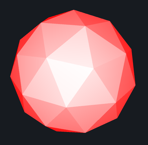
Figure 2. Dot product of view direction and plane’s normal.
On Fig. 2. you can see the shader in action. How it works? We start by computing a dot product of a view direction and a plane’s normal. The dot product of two vectors yield a scalar, which is telling us about the angle between these two vectors. Moreover when these two vectors are normalized (vector length equal 1), then the dot product is equal the cosine of the vectors angle. Hence we normalized the viewDir in our vertex shader. From trigonometry we know, that cosine value vary between -1 to 1 in way that if the angle is 0 deg the value of cos(0) = 1, if angle = 90 deg the cos(90) = 0 and if angle 180 deg cos(180) = -1.
This can be translated as follow:
- dot product of two parallel vectors pointing the same direction is 1, check the Fig. 2. for white planes located in the middle of image. The view direction vector and plane normal are pretty much parallel, just pointing at you,
- dot product of perpendicular vectors is 0, on Fig. 2 these are the cases when planes are red.
- dot product of two parallel vectors pointing opposite direction is -1. These are the back side planes of the model. As negative values do not have any sense for colour definition I am using saturation function, which clamp the value of dot product between 0 and 1. We will play with this planes later on and explore the culling option in shaders as well.
Figure 3. Shader with transparency.
Finally the get red and white colours of fragments the green and blue channels are set according to dot product value.
That is already a nice effect, but let’s make it transparent. To correctly render transparent material, make fallowing changes to your shader code:
 - in Tags change "RenderType" to "Transparent"
 - in Subshader add Blend SrcAlpha OneMinusSrcAlpha
And then add this line to your shader code:
- in fragment shader add a = 1-VNdot;
In this case the front planes will be fully transparent and the perpendicular planes will be opaque. The effect is pretended on Fig. 3. It is hard to see the effect of transparent planes as the background has solid colour but is there believe me. As far this looks already pretty cool, there is small thing I would like to add. At this moment we are not rendering the back side of the mode. This is due to the fact that in Unity default setting culling is Back. In result planes which are facing away from us are not render. If you want learn more about it visit the Unity3D documentation page about ShaderLab: Culling & Depth Testing. We have three option for culling: back, front and off. And now we will switch to front culling to render only the back side of the model.
Figure 4. Inner planes of model back side.
So add to your shader code:
- in Subshader Pass add Cull Front
And as soon as you do that, the all model turn into red hence we saturate (clamp) our dot product. So instead of saturation, we will use abs function (absolute value):
- in fragment shader change VNdot for float VNdot = abs(dot(i.viewDir, i.worldNormal));
The effect is shown on Fig. 4. This is the back side of the model. Why we see more planes (triangles) is a mystery for me. I need to check it in my model. However, to render both sides on the screen, we need create two Passes in our shader, one for back side and the second one for front side. To do so duplicate whole Pass body and in the first set Cull Front and in the second Cull Back. Yet we will make a small change to make the model looks nicer. In the first Pass (Cull Front) change the value of alpha channel for:
- in fragment shader change col.a for col.a = VNdot*0.1;
Figure 5. Rendered model with two passed for back and front culling.
Now the planes aligned with view direction are more opaque than the perpendicular one. Additionally the alpha channel is strongly attenuated just to make a slight visual effect that there is something there. The effect of this last change is presented on Fig. 5.
And that pretty much it for this shader. To finalise we will make few improvements, like moving some hard code value to properties so it will be easier to mess with in Unity inspector. In Cull Front Pass change:
- in fragment shader change a for col.a = VNdot * _BackIntensity;
_BackIntensity is now a property of the shader and can be access from Unity inspector. In the second pass we will make more changes, as we will separate main colour and rim colour. To make life easier below is the final code of the fragment shader in the second pass (cull back):
fixed4 frag(v2f i) : SV_Target
{
       float VNdot = abs(dot(i.viewDir, i.worldNormal));
       float rim = pow(1 - VNdot, _RimIntensity);

       fixed4 col = _MainColor + _RimColor*rim;
       col.a = rim + _FrontIntensity;
       return col;
}
Now the finial fragment colour is a mix of _MainColor and the colour of rim light. Another modification makes the rim value depends exponentially on a dot product instead of linear. This will impact the most a colour of planes oriented somewhere in the middle between 0 deg and 90 deg. I will definitely write a blog entry about different types of mathematical functions and what kind of effect they can create. Now I am using the exponential function to make a rim light impacts only the most perpendicular planes.
Thanks for reading, go to github to get the final version of shader if you want. And watch the video below to see what we have done today. Thanks.