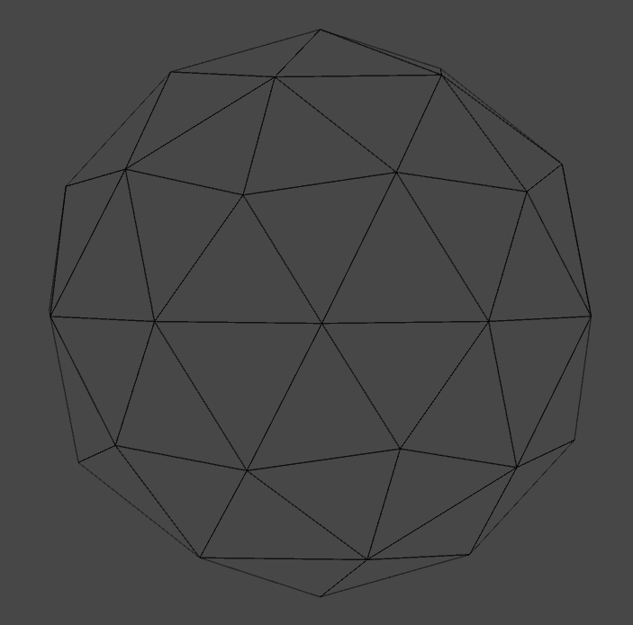
For this tutorial we will develop Grid Hologram. To do so, we will use previously created shader (Basic Hologram) and we will extend it for new functionality. You can get (Basic Hologram) from my github. As previously we will need two passes for a front and back model rendering. However, just for sake of simplicity and clarity let’s remove the first pass (the one which include Cull Front line), so we will draw only the front of model. At the end we will bring it back with few changes.

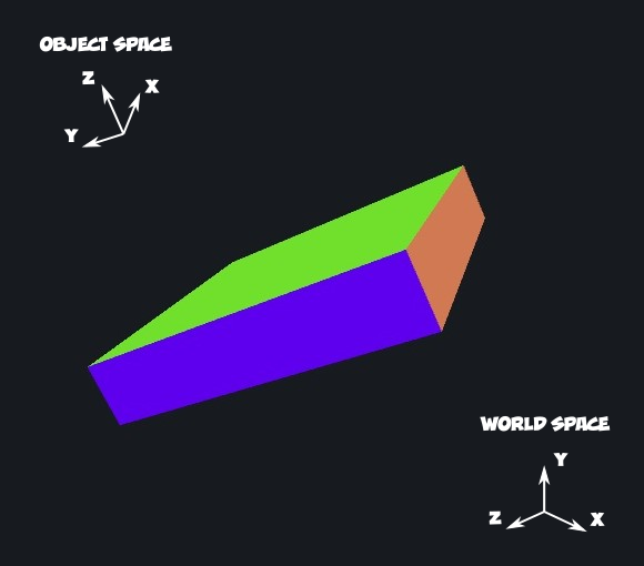
Figure 1. Main Idea behind this shader – 1D case.

I named this shader a grid hologram and what I would like to achieve is shader which will draw only lines insteded of full model. Or to be more specific looped lines in each plane of the model (x, y, z). To explain it better let’s think in one dimension for a moment. Assume our model is just line along y-axis (Figure 1). Instead of seeing a full line on our screen we want select some part of the model to be rendered as transparent and some as a transparent. As you can see from Figure 1 the choice which part is transparent or not can be determined by position of a vertex in the object space.The object vertexes have coordinate from -1 to +1 so we can write a function to check for the position of a vertex and draw a pixel (fragment) as opaque or not. However I would like to obtain a smooth transition between the opaque and transparent part of rendered model. In that case a cosine function become really handy. To work with a cosine function, we will transform the vertex coordinate values (-1 to +1) into radians (-kπ to kπ), where k is integer and it will determine number of the cosine cycle (Figure 2).

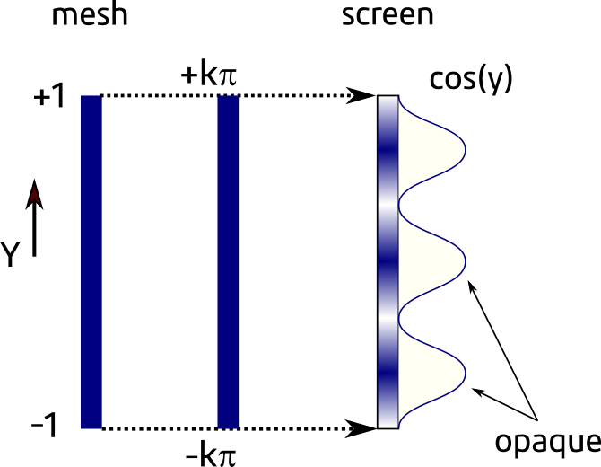
Figure 2. Cosine function of vertex object space position.

As you can see the first our task to create something like this, we need get value of the vertex position. We can do it by passing the vertex position from the vertex shader into the fragment shader.

 - in v2f struct add: float4 localVertex : TEXCOORD2;
 - in Vert Shader add: o.localVertex = v.vertex;

Before starting any calculation let’s define two useful constants π and 2π by adding:

#define PI 3.14159265
#define TWO_PI 6.2831853

And add shader property, (k integer from Figure 2) it will control number of opaque lines:

 - in properties section add: _CycleCount("Cycle Count", Range(0,40)) = 1
 - before fragment shader add: float _CycleCount;

Figure 3. 1Shader effect for _CycleCount = 3

Finally in the Fragment Shader add these lines to applied cosine function to vertex position:

 float mask = cos(PI * i.localVertex.y * _CycleCount);
 mask = (mask + 1.0) * 0.5f;
 col.a *= mask;

The effect of these changes (_CycleCount = 3), can be seen on figure 3. This already looks quite nice and it can be use for making a scanning animation by adding _Time variable inside a cosine function.

Figure 4. Grid Hologram, _CycleCount = 10, _LineDefinition = 8.

In the next step I would like to get better a line definition or even better I would like to have control of the line width. This can be achieved by applied the power function to the mask value as fallow:

 - in fragment shader add: mask = pow(mask, _LineDefinition);

_LineDefinition is a shader new property which allows us to control a width of the line. (Create it in analogical way to _CycleCount). The effect of this addition can be seen on Figure 4.

And now we need to replicate this to x- and z- axis. Please add this to your fragment shader to get effect presented on Figure 5.

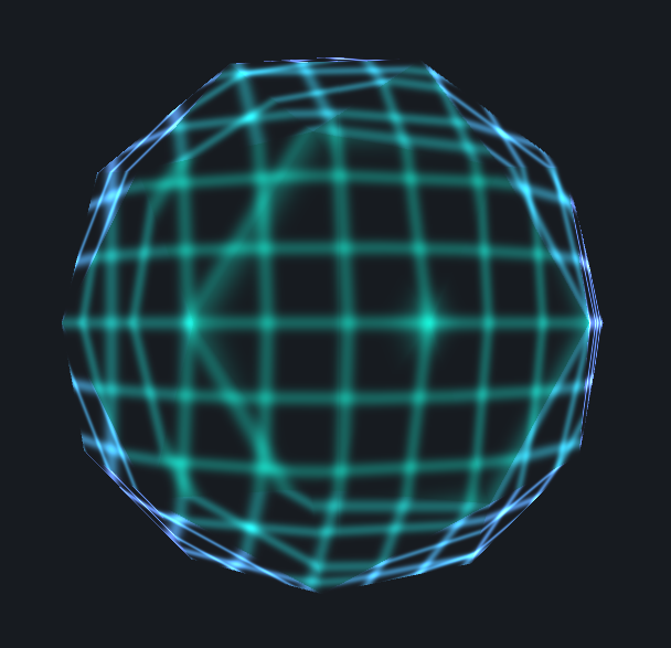
Figure 5. Drawing grid in 3D _CycleCount = 10, _LineDefinition = 8

// Y - axis
 float maskY = cos(PI * i.localVertex.y * _CycleCount);
 maskY = (maskY + 1.0) * 0.5f;
 maskY = pow(maskY, _LineDefinition);

// X - axis
 float maskX = cos(PI * i.localVertex.x * _CycleCount);
 maskX = (maskX + 1.0) * 0.5f;
 maskX = pow(maskX, _LineDefinition); 

// Z - axis
 float maskZ = cos(PI * i.localVertex.z * _CycleCount);
 maskZ = (maskZ + 1.0) * 0.5f;
 maskZ = pow(maskZ, _LineDefinition);

 float mask = (maskX + maskY + maskZ) / 3.0;


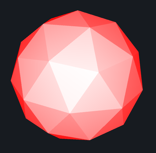
Figure 6.Grid Hologram Shader

And finally we can add back the second pass in order to draw a backside of the model.The second pass will be almost the same as first, so you can copy and past. Hoever to draw the backside of mesh change the Culling flag to Cull FRONT. For better visual effect it is good to dim a bit the colour intensity for this pass.

 - in fragment shader add: mask *= 0.1;

The final effect can be seen on Figure 6 and in video attached bellow.

And that is the end. On github you can get the final version of this shader. Thank you veru much for reading.

Figure 1. Wireframe of 3D model.

In our second Shader Adventure we will use plane’s normal to create basic holographic effect. We start with a super simple shader that paints 3D model’s planes according to a value of dot product between a plane normal and a view direction. Planes orientated parallel to the view direction, (these planes in our model are located in the middle part of Fig. 1.) will be painted by white colour. Planes, which in fact could not be seen, oriented perpendicular to the view direction will be marked by red colour. Any orientation of a plane between 0 deg and 90 deg will yield reddish colour. We will make that the green and blue channels values will depend on angle between a normal vector of plane and a view direction. And that will produce reddish colour of planes. To demonstrate this effect I will use model presented on Fig. 1. The triangles represent model planes.

So go to github and grab the  base shader or generate in Unity3D the UnLit shader (2017.2.1p4 version of Unity3D I am currently using). First let’s make change to shader code and after that we will discuss the effects of this changes. Start with:

 - in AppData struct add: float3 normal : NORMAL;
 - in v2f struct add: float3 worldNormal : NORMAL;
 - in vertex shader add: worldNormal = UnityObjectToWorldNormal(v.normal);

That makes possible to access the normal vector value in our fragment shader. However we still need the view direction for each fragment. The view direction depends on a vertex position and the position of viewer. We will calculate it for each vertex in the vertex shader by adding these lines to our shader:

 - in v2f struct add: float3 viewDir : TEXCOORD1;
 - in vertex shader: float4 worldVertex = mul(unity_ObjectToWorld, v.vertex);
 - in vertex shader: viewDir = normalize(UnityWorldSpaceViewDir(worldVertex.xyz));

Let’s explain a bit. First of all transformation of a vertex position from the object to the world space is done. Then, we use the world position of the vertex to calculate a view direction for the vertex. And now we are ready to move to a fragment shader. This is a code of my fragment shader body so copy and paste it:

fixed4 frag(v2f i) : SV_Target
{
   float VNdot = saturate(dot(i.viewDir, i.worldNormal));
   fixed4 col = fixed4(1, VNdot, VNdot, 1);                   
   return col;
}

Figure 2. Dot product of view direction and plane’s normal.

On Fig. 2. you can see the shader in action. How it works? We start by computing a dot product of a view direction and a plane’s normal. The dot product of two vectors yield a scalar, which is telling us about the angle between these two vectors. Moreover when these two vectors are normalized (vector length equal 1), then the dot product is equal the cosine of the vectors angle. Hence we normalized the viewDir in our vertex shader. From trigonometry we know, that cosine value vary between -1 to 1 in way that if the angle is 0 deg the value of cos(0) = 1, if angle = 90 deg the cos(90) = 0 and if angle 180 deg cos(180) = -1.

This can be translated as follow:

  • dot product of two parallel vectors pointing the same direction is 1, check the Fig. 2. for white planes located in the middle of image. The view direction vector and plane normal are pretty much parallel, just pointing at you,
  • dot product of perpendicular vectors is 0, on Fig. 2 these are the cases when planes are red.
  • dot product of two parallel vectors pointing opposite direction is -1. These are the back side planes of the model. As negative values do not have any sense for colour definition I am using saturation function, which clamp the value of dot product between 0 and 1. We will play with this planes later on and explore the culling option in shaders as well.

Figure 3. Shader with transparency.

Finally the get red and white colours of fragments the green and blue channels are set according to dot product value.

That is already a nice effect, but let’s make it transparent. To correctly render transparent material, make fallowing changes to your shader code:

 - in Tags change "RenderType" to "Transparent"
 - in Subshader add Blend SrcAlpha OneMinusSrcAlpha

And then add this line to your shader code:

 - in fragment shader add a = 1-VNdot;

In this case the front planes will be fully transparent and the perpendicular planes will be opaque. The effect is pretended on Fig. 3. It is hard to see the effect of transparent planes as the background has solid colour but is there believe me. As far this looks already pretty cool, there is small thing I would like to add. At this moment we are not rendering the back side of the mode. This is due to the fact that in Unity default setting culling is Back. In result planes which are facing away from us are not render. If you want learn more about it visit the Unity3D documentation page about ShaderLab: Culling & Depth Testing. We have three option for culling: back, front and off. And now we will switch to front culling to render only the back side of the model.

Figure 4. Inner planes of model back side.

So add to your shader code:

 - in Subshader Pass add Cull Front

And as soon as you do that, the all model turn into red hence we saturate (clamp) our dot product. So instead of saturation, we will use abs function (absolute value):

 - in fragment shader change VNdot for float VNdot = abs(dot(i.viewDir, i.worldNormal));

The effect is shown on Fig. 4. This is the back side of the model. Why we see more planes (triangles) is a mystery for me. I need to check it in my model. However, to render both sides on the screen, we need create two Passes in our shader, one for back side and the second one for front side. To do so duplicate whole Pass body and in the first set Cull Front and in the second Cull Back. Yet we will make a small change to make the model looks nicer. In the first Pass (Cull Front) change the value of alpha channel for:

 - in fragment shader change col.a for col.a = VNdot*0.1;

Figure 5. Rendered model with two passed for back and front culling.

Now the planes aligned with view direction are more opaque than the perpendicular one. Additionally the alpha channel is strongly attenuated just to make a slight visual effect that there is something there. The effect of this last change is presented on Fig. 5.

And that pretty much it for this shader. To finalise we will make few improvements, like moving some hard code value to properties so it will be easier to mess with in Unity inspector. In Cull Front Pass change:

 - in fragment shader change a for col.a = VNdot * _BackIntensity;

_BackIntensity is now a property of the shader and can be access from Unity inspector. In the second pass we will make more changes, as we will separate main colour and rim colour. To make life easier below is the final code of the fragment shader in the second pass (cull back):

fixed4 frag(v2f i) : SV_Target
{
       float VNdot = abs(dot(i.viewDir, i.worldNormal));
       float rim = pow(1 - VNdot, _RimIntensity);

       fixed4 col = _MainColor + _RimColor*rim;
       col.a = rim + _FrontIntensity;
       return col;
}

Now the finial fragment colour is a mix of _MainColor and the colour of rim light. Another modification makes the rim value depends exponentially on a dot product instead of linear. This will impact the most a colour of planes oriented somewhere in the middle between 0 deg and 90 deg. I will definitely write a blog entry about different types of mathematical functions and what kind of effect they can create. Now I am using the exponential function to make a rim light impacts only the most perpendicular planes.

Thanks for reading, go to github to get the final version of shader if you want. And watch the video below to see what we have done today. Thanks.

I decided to start this journey by visiting a normal vector. Just to be sure we are all on the same page a few words about the normal vector. In 3D space a vector which is orthogonal (perpendicular) to a plane, it is called a normal of this plane. This means that the normal vector defines the plane orientation is 3D space. There is massive number of online resources about this subject, so if you want learn more just google it. But now we just move to coding.

I will start with my base shader. It is just very simple vertex and fragment shader. You can download it from my github Base Shader or in Unity3D (I have done that for Unity3D 2017.2.1p4)  hit Create/Shader/Unlit Shader. Then open this shader and (i) remove lines related to a fog and (ii) removed the shader level of detail (LOD 100) line. Of course this is a quite boring shader. It will render a white flat object only. However it is perfect starting points, and we will build from it.

First we will explore normals in an object space and present them with RGB colours. The good news is that each vertex has already an information about normal vector, so we need only access it. To do so we will make following changes in our shader code:

 - in AppData struct add: float3 normal : NORMAL;
 - in v2f struct add: float3 normal : NORMAL;
 - in vertex function add: o.normal = v.normal;

Now we can access the normal data in our fragment shader. To show normal values, we will draw planes having RGB colour according to theirs space orientation, namely planes which are oriented along x-axis in red colour, y-axis in green and z-axis in blue. To make it happen, frag function needs to change:

 - in fragment shader comment: texture sampling line of code
 - in fragment shader add: fixed4 col = fixed4(abs(i.normal.r), abs(i.normal.g), abs(i.normal.b), 1);

Figure 1. Normals in Object Space

On Fig. 1. we can see the effect of this shader on a box model. Because the values of normals are taken from the Object Space, colours of box faces will not change under box rotation. Of course we can also see how normals for this model look like in World Space. To do so we will use Unity3D predefined function:

 - in v2f struct add: float3 worldNormal : TEXCOORD1;  // field for our new normal data
 - in vertex shader add: o.worldNormal = UnityObjectToWorldNormal(v.normal); // unity helper function to compute world space normal
 - in fragment shader replace normal by worldNormal:
fixed4 col = fixed4(abs(i.worldNormal.r), abs(i.worldNormal.g), abs(i.worldNormal.b), 1);

Figure 2. Normals in World Space

If your shader is attached to any object, you should see the difference immediately. If not try to rotate object, to be sure that the Object Space is not perfectly aligned with the World Space. The shader impact on my box model is presented on Fig. 2. Now the colours are related to World Space as  expected. Since the object is not perfectly aligned with the World Space coordinate system the RGB channels of faces colours are mixed.

Can we make something funny with this? Of course we can :). Let’s use normal values as a mask. To make it much funnier I will use one of my B&W photo as a texture (Fig. 3). So change fragment shader as follow:

 - in fragment shader uncomment: texture sampling line fixed4 col = tex2D(_MainTex, i.uv);
 - in fragment shader calculate mask value: float mask = step(0.5, abs(i.normal.b)); // you can use worldNormal as well. 0.5 is threshold value you can put it to shader properties for easy testing
 - in fragment shader multiply colour by mask: col *= mask;
 - in fragment shader keep alpha channel equal 1: col.a = 1.0;

Figure 3. Object with Texture

Fig. 3. shows the model of box when the effect is not applied. And video bellow shows the result of the shader for both the World and Object Space normal. You can see that faces of box which are not aligned along z-axis is drawn black instead of taking values from texture. And that is all for now. Thanks for reading.

Recently I invested a bit of my time to learn how to write Shaders for Unity3D. I read books, watched tutorials, took online course etc. There are truly amazing teachers out there. But writing shaders is not only about knowledge it is actually mostly about the practice.

So I decided to start a small project, where I will experiment with Shaders. Sort of travel blog, but instead of exploring real world, we will wander in 3D computer graphics shaders space. Hopefully this will be useful for you and just to let you know I am still learning how to program shaders so please feel free to correct me if you find any mistake.

I have started github repository, where I will keep shaders built for this project. So in many cases I will not show the full shader code here. Instead I’d like to focus on important for a blog post parts of shaders. But I will make everything as easy as possible so you can replicate it.


GitHub Shaders Library